RhinoPower Ltd

Members Login
Username 
 
Password 
    Remember Me  
Post Info TOPIC: ECU ID 1902, P/N #33920-65DA1


Guru

Status: Offline
Posts: 1351
Date:
RE: ECU ID 1902, P/N #33920-65DA1
Permalink  


The resistor affects the fuelling over the whole load range, its a substitute for the Long Term Fuel Trim. I think maybe the FSM is a little confusing, its more a case that the CO reading at idle is used to set the trim.


__________________

1984 Suzuki SJ413K pick up, 1.6 16V Baleno engine
2000 Suzuki Vitara 1.6 8V, many mods
2004 Suzuki Ignis 1.5VVT 4Grip
2006 Suzuki Jimny 1.3VVT JLX+
and many more.


Senior Member

Status: Offline
Posts: 196
Date:
CO adjusting resistor
Permalink  


Out of curiosity - have you ever looked at the code for this?  Does this resistor affect fuelling at all rpm or just at idle?  The FSM suggests the resistor is used to adjust CO at idle, but I have recollections of the guys on the TeamSwift forum suggesting it could be used for general enrichment. 


__________________


Guru

Status: Offline
Posts: 1351
Date:
RE: ECU ID 1902, P/N #33920-65DA1
Permalink  


I need to test this on the Vit, now I have it at home. The results that I was getting from the Baleno didn't seem to be what I was expecting either. I have done some work on the code for the fast idle for the 8V Vit/Track/Kick so I will be able to perform a code trace while logging. I need to get an ECU set up for that, currently I am doing some other work on the system supervisor IC, I'd like to get that done before I clear the bench to do something else. At the moment the Suzuki ECU stuff is a bit of a rainy day project, the "good" news is that rain is forecast for later this week!


__________________

1984 Suzuki SJ413K pick up, 1.6 16V Baleno engine
2000 Suzuki Vitara 1.6 8V, many mods
2004 Suzuki Ignis 1.5VVT 4Grip
2006 Suzuki Jimny 1.3VVT JLX+
and many more.


Senior Member

Status: Offline
Posts: 196
Date:
Permalink  
 

I can't quite make up my mind about the target idle - the change or direction of the change seems to be right, but the actual numbers confuse the issue somewhat.

Using address 8 and tidlegain of 7.8125, key on, engine off, overnight cold, target idle shows a value of - I believe - 1218, but the engine starts & idles quite a bit higher than that, around 1800 rpm and the actual idle drops much faster than the target idle does...

T-IDLE      RPM

1218        1780

1203        1265

1101        1129

1093        1102

1062        1061

1046        1048

1031        1035

1015        1006

1000          968

Once the engine has warmed the targe idle will hold reasonably constant around the numbers mentioned earlier - the rpm tends to vary somewhat, but will generally follow the target idle.

In case it makes a difference - as far as I'm aware, on this engine, the ECU controls the fast idle via the idle air control valve - there is a coolant hose through the throttle body, but it seems to warm the throttle body (perhaps to prevent icing) as the FSM does not document any "thermo-wax" type fast-idle mechanisms, as it does for the V6 engined version.


__________________


Guru

Status: Offline
Posts: 1351
Date:
Permalink  
 

Good stuff, there will be quite a few flags that won't apply to your vehicle, O2 status, EGR and all the auto stuff.I think that you've probably got most of the flags that apply to you.

The old idle switch used to be set so it switched at 0.5V. On the 16Vs that I have looked at the code simply takes 0.5V as the limit of the idle range, I think that we saw that when you looked at the TPS originally. The idle flag remains because it is used for all sorts of functions internally, it may also be used to set the TPS accurately.


__________________

1984 Suzuki SJ413K pick up, 1.6 16V Baleno engine
2000 Suzuki Vitara 1.6 8V, many mods
2004 Suzuki Ignis 1.5VVT 4Grip
2006 Suzuki Jimny 1.3VVT JLX+
and many more.


Senior Member

Status: Offline
Posts: 196
Date:
Permalink  
 

I spent some time fooling around with the status flags - found some interesting stuff.

Address 37, bit 7 is on for an electrical load (lights & rear defog seem to be the only two sensed - based on the ECU wiring)

Address 37, bit 2 is on if the fuel pump is on.

Address 37, bit 0 is on - I have no idea why.

Address 38, bit 4 is on if the throttle is closed (idle), but there is no idle switch, the TPS is a 3 wire resistor.

Address 38, bit 2 is a/c related, we'll come back to it in a minute.

Address 38, bit 1 is the power steering pump.

Address 39, bits 4 & 5 are a/c related also, and again we will come back to them

Address 39, bit 0 is the blower fan.

OK - back to the a/c related bits now - as far as I can tell ...

Address 38, bit 2 indicates that the a/c has been "commanded on" - the blower fan must be on and the a/c button depressed - it does not mean that the a/c system is  on, because there are several other "circumstances" that inhibit or disable the a/c system, for example if the engine is not running, the a/c control will not energize the compressor or condenser fan.

Also of note, if the engine over temps or the CTS fails, the ECU will enable the condenser fan (which is under direct ECU control), and disable the compressor clutch (via an a/c cut signal sent to the a/c amplifier).

This takes us to ...

Address 39 bit 4 is apparently the a/c compressor clutch and bit 5, the a/c condenser fan.

With the ignition on engine off, if the a/c is switched on 38-2 will go high, 39-4 & 5 stay low until the engine is started.

If the a/c is switched on/off all three bits change together, if the system is left running until the compressor cycles off, 38-2 stays on, 39-4 & 39-5 go off and come back on with the compressor, typically 39-4 will go low before 39-5, but they go high together.

If a CTS failure is forced, 39-5 comes on with the ignition, as does the condenser fan, if the a/c is switched on, 39-4 stays low and the compressor stays off.


__________________


Guru

Status: Offline
Posts: 1351
Date:
Permalink  
 

I haven't changed any settings so I don't know why you can't edit your posts. I'll try and have a look at that, I very rarely ever use the admin stuff so I'm not at all familiar with it.

The battery voltage display is probably just a floating point formatting issue so I'll look at that tonight. I need to sit down and get the status viewer up and running. I've been busy going over the 8v stuff lately, I finally got the Vit to the new house so I'm having a play with it.


__________________

1984 Suzuki SJ413K pick up, 1.6 16V Baleno engine
2000 Suzuki Vitara 1.6 8V, many mods
2004 Suzuki Ignis 1.5VVT 4Grip
2006 Suzuki Jimny 1.3VVT JLX+
and many more.


Senior Member

Status: Offline
Posts: 196
Date:
Permalink  
 

I don't seem to be able to edit my posts anymore confuse.

Anyway - I have arbitrarily assigned the addresses to Status Flags 1, 2 & 3 - and can see them change in the dataviewer, as I switch the various items on & off - a/c compressor, blower, lights/defroster, power steeting - I don't think the status flag viewer is fully implemented, so I can shuffle them around later if/as required.

One other thing - in the formatted data viewer, I notice my battery voltage showing a constant 13.0V, although the virtual dashboard displays the battery voltage correctly.


__________________


Senior Member

Status: Offline
Posts: 196
Date:
Permalink  
 

I think I've located the "target idle" at address 8 - I entered it in the datastream file, along with 7.8125 as the tidlegain and get 750 as the target with a/c off and 796 with a/c on, I will confirm this on the next cold start (probably tomorrow morning).


Also status flags at addresses 37, 38 & 39.


__________________


Guru

Status: Offline
Posts: 1351
Date:
Permalink  
 

From those readings I get this:

Advance slope


The erset may bahave differently on the GV, on the Vit is resets all parameters stored in RAM. I will have to check a couple of others, I'm not sure which parameters your GV is storing as the fuel trim is set by the AFR adjust resistor.


__________________

1984 Suzuki SJ413K pick up, 1.6 16V Baleno engine
2000 Suzuki Vitara 1.6 8V, many mods
2004 Suzuki Ignis 1.5VVT 4Grip
2006 Suzuki Jimny 1.3VVT JLX+
and many more.


Senior Member

Status: Offline
Posts: 196
Date:
Permalink  
 

OK - here's what we found comparing the virtual dash and the timing light.


Engine rpm - RV IGN ADV - Timing Light ADV

Idle (800 rpm) .134 = 14* ..........14*

2000 rpm ........  73 = 35* ..........41*

3000 rpm ........  59 = 40* ..........52*

4000 rpm ........  50 = 43* ..........66*

They both advance with rpm, but the amount of advance does not quite match.


Another question - this time related to ECU reset.

Is it possible that there are different levels or stages of "reset"?

Whilst exploring the fault code analysis, I reset the ECU several times using RV, and other than the dashboard CEL and the RV MIL going off, there seemed to be no other changes in engine operation.

Having put RV aside temporarily, I took the battery out of the vehicle to deal with some corrosion on the battery stand and the inner wing below the battery stand, and having completed that task, replaced the battery and reconnected - I would estimate the battery was out of the vehicle for between 6~8 hours.

When the vehicle was restarted I noted a distinct difference in the way the engine ran - a cold start would normally result in the vehicle initially idling at around 1500 rpm, with the idle dropping gradually back to 1200 and eventually ~850 rpm - on startup after reconnecting the battery it idled at around 900 rpm.

During the following morning, the idle was consistently lower than normal and at some points during the morning it would not idle, the rpms would gradually drop and then the engine would stall - switching the a/c on would force an idle at around 900 rpm - by afternoon of the first day, the idle situation had improved considerably, and by noon of the second day, it seems to be back to normal.

Is it possible that disconnecting the battery causes the ECU to lose ALL stored parameters, but resetting it (as with RV), simply clears the error flags?


__________________


Guru

Status: Offline
Posts: 1351
Date:
Permalink  
 

That would need to be confirmed with a timing light, correcting for the adjustment that you've made to the base timing. I get different values for the early 16V but the 5 looks about right, what does the FSM say it should be?

It confused me too, partly because its backwards and partly because the IAT flow on the 1112 gives values that seem to correspond exactly with the ignition timing on the Vit.


__________________

1984 Suzuki SJ413K pick up, 1.6 16V Baleno engine
2000 Suzuki Vitara 1.6 8V, many mods
2004 Suzuki Ignis 1.5VVT 4Grip
2006 Suzuki Jimny 1.3VVT JLX+
and many more.


Senior Member

Status: Offline
Posts: 196
Date:
RE: ECU ID 1902, P/N #33920-65DA1 - Igntion advance
Permalink  


One of the datastream addresses that has given me trouble is the ignition advance, so when I came across a thread in the Suzuki forums where you were discussing RV with Bex, and igntion advance came up, I took notice.

In that thread you say ...

Ign advance is shown as raw binary, the conversion factor is -0.3528*value + 61.224. 160 = 5degs so the ECU is pulling timing as expected.

Based on this, I took a look at the raw data in the dataviewer, and selected an address (14) that showed 160 key on, engine off, and entered it into the datastream config file - RV now shows the following in the virtual dashboard.

Engine off - advance is 160 (5* BTDC)

Engine at idle (~850 rpm) - advance is 134 (13* BTDC)

Engine at 3000 rpm - advance is 50 (43* BTDC)

Do those numbers look about right?


__________________


Guru

Status: Offline
Posts: 1351
Date:
RE: ECU ID 1902, P/N #33920-65DA1
Permalink  


fordem wrote:

Seems simple enough - if I follow the list you provided in this thread - the first time around I only entered "active" fault codes and RV spat out an "access violation" error dialogue everytime I clicked "update" in the fault code viewer, a quick copy & paste fixed that, and I subsequently went back and entered a "55" in all the unused functions.


The code 55 is intended to trap codes that aren't defined, some of the later models have codes that don't set the MIL and therefore aren't listed in the FSM. I may tweak that code so it automatically fills in a Code 55 if there is no number entered.

I still have around 30 more definitions to enter so there will be changes to that file.


__________________

1984 Suzuki SJ413K pick up, 1.6 16V Baleno engine
2000 Suzuki Vitara 1.6 8V, many mods
2004 Suzuki Ignis 1.5VVT 4Grip
2006 Suzuki Jimny 1.3VVT JLX+
and many more.


Senior Member

Status: Offline
Posts: 196
Date:
Permalink  
 

I attempted to edit my previous post on the VSS failure sensing but couldn't - whilst flipping through the FSM I came across the following under the troubleshooting for a Code 24 (VSS) ...

Vehicle speed signal not inputted although fuel is kept cut for longer than 5 seconds

I believe fuel cut occurs if the throttle is closed with the rpm over a certain figure, so essentially, if the vehicle is on the overrun for longer than 5 seconds, it has to be moving (if not the rpm would drop to idle in less than 5 seconds), and VSS should be "inputted".


__________________


Senior Member

Status: Offline
Posts: 196
Date:
Permalink  
 

Seems simple enough - if I follow the list you provided in this thread - the first time around I only entered "active" fault codes and RV spat out an "access violation" error dialogue everytime I clicked "update" in the fault code viewer, a quick copy & paste fixed that, and I subsequently went back and entered a "55" in all the unused functions.

I only tested two codes - IAT & ECT open - I'll run through them all in daylight.


__________________


Guru

Status: Offline
Posts: 1351
Date:
Permalink  
 

fordem wrote:

OK - is adding these to the faultcode.csv file a simple task - or should I just be patient?


Have a go at it and then you can tell me how simple it is. I've used a slightly different layout in the faultcodes file to try and make it easier to understand. At the top of the file is a list of the codes and strings each fault has been allocated a function number. Under that is a list of the fault code addresses and bits with the ECU ID as the column header. Fill in the function number that corresponds to the bit and it should all work as if by magic smile


__________________

1984 Suzuki SJ413K pick up, 1.6 16V Baleno engine
2000 Suzuki Vitara 1.6 8V, many mods
2004 Suzuki Ignis 1.5VVT 4Grip
2006 Suzuki Jimny 1.3VVT JLX+
and many more.


Senior Member

Status: Offline
Posts: 196
Date:
Permalink  
 

OK - is adding these to the faultcode.csv file a simple task - or should I just be patient?


__________________


Guru

Status: Offline
Posts: 1351
Date:
Permalink  
 

OK so with what you've found, the list from the FSM and knowing that the codes are ordered we now have:

Address1

7

6

5

4 - Code 43

3 - Code 42 - CMP

2 - Code 41 - CKP ?

1 - Code 34 - MAF

0 -  Code 33 - MAF

Address 0

7 = Code 25 IAT Low

6 = Code 24 - VSS

5 = Code 23 - IAT High

4 - Code22 - TPS

3 - Code 21 - TPS

2 - Code 15 - CTS Low 

1 - Code 14 - CTS High

0 -  Code 13 - O2 Sensor   (which you don't have!) 


That leaves:

51 - which you won't have

71 - my guess is the 7x codes are higher up in memory

72

75

76

8x - immobiliser which you don't have should be higher up in memory


__________________

1984 Suzuki SJ413K pick up, 1.6 16V Baleno engine
2000 Suzuki Vitara 1.6 8V, many mods
2004 Suzuki Ignis 1.5VVT 4Grip
2006 Suzuki Jimny 1.3VVT JLX+
and many more.


Senior Member

Status: Offline
Posts: 196
Date:
Permalink  
 

OK - I'll wait to hear from you before doing "sensor low/short to ground" fault simulation - it's something I'm less than comfortable with ;) .

A disconnected VSS will give a 64 in addresses 0 & 3 - I have been unable to determine exactly what circumstances trigger it though - you can drive some distance without it being sensed, and although it always seems to be sensed with the vehicle on the "over run", I was unable to trigger it by alternately driving & coasting (clutch up, throttle closed) - I suspect the vehicle may have to be on the over run for more than a particular number of seconds - presumably it's looking at rpm, mass air flow & throttle position to detect when it's on the over run.

By the way - you can reset the ECU on the fly - which will immediately clear the dashboard CEL, but disrupts communications with RV - you can sometimes get comms back by requesting the ECU ID, but as before the MIL stays yellow until RV is closed & reopened.


-- Edited by fordem on Saturday 21st of May 2011 09:11:29 PM

__________________


Guru

Status: Offline
Posts: 1351
Date:
Permalink  
 

I took a look at the FSM myself, I think that the first byte can be filled in by using the list and the locations already known, that should include the position for the VSS, it was the 32 for the MAF that was confusing me. I will check my notes and post back.


__________________

1984 Suzuki SJ413K pick up, 1.6 16V Baleno engine
2000 Suzuki Vitara 1.6 8V, many mods
2004 Suzuki Ignis 1.5VVT 4Grip
2006 Suzuki Jimny 1.3VVT JLX+
and many more.


Senior Member

Status: Offline
Posts: 196
Date:
Permalink  
 

I tried to do some fault code logging, but the weather was not very co-operative, so I called an early halt.

Here's what I have so far.

My ECU can only show a limited number of errors - based on the FSM - I can have the following.

12 - Normal

14 & 15 - ECT

21 & 22 - TPS

23 & 25 - IAT

24 - VSS

33 & 34 - MAF

42 - CMP (cam position)

ECT - open - gives a 2 in addresses #0 & #3

TPS - open - gives a 16 in addresses #0 & #3

IAT - open - gives a 32 in addresses #0 & #3

MAF - open - gives a 2 in addresses #1 & #4

CMP - open - gives an 8 in addresses #1 & #4

"Active" faults seem to be addresses #0 & #1, "stored" faults at addresses #3 & #4.

The ECU will detect all of the above in "key on, engine off" with the exception of CMP - the engine must be cranked for it to detect the lack of cam positioning pulses, and even though an open CMP will put an 8 in address #4, this will be cleared if the CMP is reconnected and the engine started so a failed (or failing) CMP sensor does not store a code.

Apparently there is no code set for a failed CKP - crank position sensor.

I'm curious as to how it will detect a failed VSS sensor, presumably the vehicle has to be in motion for this, but, how can it distinguish between a failed VSS and a stationary vehicle?

Anyway - testing the VSS would have meant sliding under the vehicle to disconnect it and then driving - which I was quite disinclined to do, given the inclement weather, which deteriorated from a spotty drizzle when I started, to a rather heavy downpour, putting an early halt to the proceedings.

We'll see what the weather is like tomorrow or maybe next weekend - I have to get under there to do an oil & filter change within the next hundred miles or so.

One observation - it seems the only way to clear a yellow MIL indicator is to close & re-open RV, I can reset the ECU, and see the stored code disappear using the dataviewer, but the MIL remains yellow.

Edit

I just noticed - this round of testing indicates a 2 for a MAF error, and my previous post says 32 - I will recheck this on the next "go-round".

Further edit - I found the scrap of paper with the jottings from the previous test - MAF error is a 2, seems a typo crept in whilst I was posting.

-- Edited by fordem on Saturday 21st of May 2011 05:00:32 PM


-- Edited by fordem on Saturday 21st of May 2011 05:05:39 PM

__________________


Guru

Status: Offline
Posts: 1351
Date:
Permalink  
 

fordem wrote:

One more fault - unplugging the MAF gives a 32 in address 1 (and stalls the engine) - going from memory - it won't idle if the MAF is unplugged - it will run if you hold it on the throttle, although it stumbles badly and is very rich.


 What CEL code do you get?


__________________

1984 Suzuki SJ413K pick up, 1.6 16V Baleno engine
2000 Suzuki Vitara 1.6 8V, many mods
2004 Suzuki Ignis 1.5VVT 4Grip
2006 Suzuki Jimny 1.3VVT JLX+
and many more.


Guru

Status: Offline
Posts: 1351
Date:
Permalink  
 

It should be possible to create the correct ECU from a different one by swapping configuration resistors but I have very limited knowledge of the variants of these ECUs.

Off the shelf resistors can be used, the lower the tolerance the more accurate the end measurement, if you use the values shown in the graph in the FSM then you can get the raw data output for each temperature and then calculate the slop and offset correction from the results.

We found two addresses for the MAF, currently RV only supports the high byte which will give a rduced resolution. The config file is due to be restructured soon to allow selective polling, at that point I will add more support for other functions and for the diesel models.

I will add code 32, looking at the list of codes in the FSM I think that we can map the first byte, the second byte seems to only use 7-bits, unless there is a code that doesn't get reported by the MIL.

The ECU stores codes but they are only accessible using a scan tool, it is very useful when trying to fault find an intermittent fault.


__________________

1984 Suzuki SJ413K pick up, 1.6 16V Baleno engine
2000 Suzuki Vitara 1.6 8V, many mods
2004 Suzuki Ignis 1.5VVT 4Grip
2006 Suzuki Jimny 1.3VVT JLX+
and many more.


Guru

Status: Offline
Posts: 1351
Date:
Permalink  
 

fordem wrote:

One more question - what happens if I reset the ECU with the engine running?


Good question - it looks like you can't. The ECU will reset on the next power up, that should be recorded somewhere I'll have to go back through my notes.


__________________

1984 Suzuki SJ413K pick up, 1.6 16V Baleno engine
2000 Suzuki Vitara 1.6 8V, many mods
2004 Suzuki Ignis 1.5VVT 4Grip
2006 Suzuki Jimny 1.3VVT JLX+
and many more.


Senior Member

Status: Offline
Posts: 196
Date:
Permalink  
 

One more question - what happens if I reset the ECU with the engine running?


__________________


Senior Member

Status: Offline
Posts: 196
Date:
Permalink  
 

If you find an ECU for a 2.0 GV with 5 speed and no O2 sensor at a reasonable price, let me know - not that I need one but I'd like to have a spare - it looks like we'll be having a second one of these in the near future, my daughter & son-in-law are looking at a couple of burgandy & silver 98s.

What resistors do we need?  If they are standard off the shelf values I can pick those up here.

Something else that I forgot to mention - in earlier discussions you mentioned the MAF as having high & low bytes, but, unless I'm missing something, there's only one address in the list of datastream functions.

One more fault - unplugging the MAF gives a 32 in address 1 (and stalls the engine) - going from memory - it won't idle if the MAF is unplugged - it will run if you hold it on the throttle, although it stumbles badly and is very rich.

The ECU reset seemed to work - but I only tried it once - I was under the impression the ECU didn't store codes, primarily because the dashboard CEL goes out as soon as the sensor is reconnected.


__________________


Guru

Status: Offline
Posts: 1351
Date:
Permalink  
 

I need to look at the settings problem, it seemed to work OK for me but TheZuke reported a problem as well.

I still haven't seen a GV ECU at a reasonable price and I haven't yet had one in for repair. If you PM me an address I'll send you some resistors and we can do a proper tempearture calibration.

There isn't currently any fault code mapping for your ECU but looking back through this thread it looked like the addresses were 0 and 1 for current faults and 2 and 3 for stored faults., the screen captures showed were you had been testing sensors. You are correct on the colours, you can also open the fault code viewer by clicking on the MIL. Did you try the fault code reset? I have tried it on the Baleno but it doesn't seem very reliable on the vehicle, its OK on the bench but I think that I need to modify that code.

The Dashboard doesn't work properly with ECU ID 0000 so I close it. You don't need to use 0000, you can just change the Dataviewer to display raw data.

The stored codes use the same mapping as the current codes and the codes are usually ordered as a 16-bit number. So far we can deduce:

Address1

7

6

5

4

3

2

1

0

Address 0

7 = IAT Low Code 25

6 = VSS Code 24

5 = IAT High Code 23

4

3

2

1 -   CTS High Code 14

0 - O2 Sensor   Code 13 (which you don't have!)             

You can link across the sensor connectors to confirm the IAT Low and CTS low codes - there is no danger of damaging the ECU! What happens when you unplug the CO adjust resistor?

TPS, MAF, crank and cam sensors can be unplugged to test, you'll have to crank it briefly to get the crank/cam signals


__________________

1984 Suzuki SJ413K pick up, 1.6 16V Baleno engine
2000 Suzuki Vitara 1.6 8V, many mods
2004 Suzuki Ignis 1.5VVT 4Grip
2006 Suzuki Jimny 1.3VVT JLX+
and many more.


Senior Member

Status: Offline
Posts: 196
Date:
Permalink  
 

Well - today is a holiday here, and although it didn't go the way I had hoped, I did find the time to take a look at 0.82 - unfortunately, I didn't have the luxury of starting with the engine cold, so I can't really comment on the new temperature scaling - so what I will say is the screen displays are slightly low compared to my IR gun, 2* or so - I'll see if I can find the time to observe those from a cold start on the week end.

A few other things I did notice are - it doesn't quite seem to retain the comms settings - at least, it didn't on the first two or three restarts, but it did after that - also the mpg indicator will slowly climb to 50 with engine idling and the vehicle stationary, I think it should do the opposite, gradually drop to zero.

When I connect I get a message "Fault code analysis not available for this ECU" - but despite this, the MIL indicator does work - I note that it seems to display three colors - black (or off), yellow & red - presumably red indicates an "active fault" because I can match that against the dashboard's CEL, and yellow indicates a "stored fault".

Looking at the data viewer (with a 0000 ECU ID) - a black MIL corresponds to the first four addresses at 0 0 0 0, unplugging the IAT gave 32 0 0 32, reconnect it gives me 0 0 0 32 - unplugging the CTS gave 2 0 0 34 and reconnecting it gave 0 0 0 34.

Question - is there a way to go from the dataviewer back to the main display without closing & re-opening the application?


__________________


Senior Member

Status: Offline
Posts: 196
Date:
Permalink  
 

For some strange reason, I've been here at least once a day, every day, and these posts never showed as new confuseanyway, I downloaded 0.82 the day it was released - just haven't found the time to do anything with it.


__________________


Guru

Status: Offline
Posts: 1351
Date:
Permalink  
 

fordem wrote:


More to the point - none of the addresses on either page seems to relate to ignition timing - I've tried inserting & removing the jumper, both at idle and at higher rpms. and none of the addresses seem to change as the jumper was inserted and removed.


 Another new(ish) piece of information - You can't fix the timing while scanning except by command from the scan tool.

On the ECUs that we've fully hacked the value moves inversely proportional to the timing.


__________________

1984 Suzuki SJ413K pick up, 1.6 16V Baleno engine
2000 Suzuki Vitara 1.6 8V, many mods
2004 Suzuki Ignis 1.5VVT 4Grip
2006 Suzuki Jimny 1.3VVT JLX+
and many more.


Guru

Status: Offline
Posts: 1351
Date:
Permalink  
 

fordem wrote:

For WTS I've been using a gain of 1 and an offset of 84, for ATS, a gain of 1 and an offset of 81.


Once you've got v0.82 we can try a few more experiments.

Try 0.925 and 74 for the temp. sensors, those seem to be fairly common values.

On most of the other ECUs the first four addresses are fault codes so unplugging a few sensors one at a time should confirm that

Address 4 or 5 is probably the target idle. So you should see that value decrease as the engine warms up.

We'cve learnt a lot more since we last looked at this ECU so we should be able to work out a few more addresses.


__________________

1984 Suzuki SJ413K pick up, 1.6 16V Baleno engine
2000 Suzuki Vitara 1.6 8V, many mods
2004 Suzuki Ignis 1.5VVT 4Grip
2006 Suzuki Jimny 1.3VVT JLX+
and many more.


Senior Member

Status: Offline
Posts: 196
Date:
Permalink  
 

No - the cam position sensor sensor can be rotated to set the 'base' timing.

The correct way to set the timing, is to freeze the ignition timing, either using the Tech1 tool, or by inserting a jumper in the diagnostic connector, and then using a timing light, rotate the CMP sensor to set the timing to 5* BTDC.

You can set the base timing by the book (5* BTDC) - or - you can set the base timing where you choose, within the limits of the adjustment slot on the CMP sensor housing.

__________________


Guru

Status: Offline
Posts: 1351
Date:
Permalink  
 

You mentioned that you run the timing further advanced, is this done by adjusting a resistor. Some other distibutorless Suzukis have this system, the timing correction is also one of the diagnostic outputs.

__________________

1984 Suzuki SJ413K pick up, 1.6 16V Baleno engine
2000 Suzuki Vitara 1.6 8V, many mods
2004 Suzuki Ignis 1.5VVT 4Grip
2006 Suzuki Jimny 1.3VVT JLX+
and many more.


Senior Member

Status: Offline
Posts: 196
Date:
Permalink  
 

No - 0.625 Gain and 40 offset don't do it for me - I started with an intake air temp that seemed plausible at 32*C and ended up with 45*C, when the actual outdoor temps were 28*C and 30*C

__________________


Senior Member

Status: Offline
Posts: 196
Date:
Permalink  
 

For WTS I've been using a gain of 1 and an offset of 84, for ATS, a gain of 1 and an offset of 81.

The difference in the offset may relate to how I have been measuring the coolant temperatures - the CTS on this engine is on the back of the head, between the engine and the firewall and for convenience I've been using a contact thermistor a foot or so away where the radiator top hose connects to a metal pipe  leading back to the CTS location - there's probably a few degrees drop across the pipe.

__________________


Senior Member

Status: Offline
Posts: 196
Date:
Permalink  
 

I don't recall what I have set right now, but I'll take a look and try those later during the day.

Thanks much.

__________________


Guru

Status: Offline
Posts: 1351
Date:
Permalink  
 

For temperature scaling the 'magic numbers' appear to be gain = 0.625, offset = 40. These values seem to work on a number of different ECUs.

__________________

1984 Suzuki SJ413K pick up, 1.6 16V Baleno engine
2000 Suzuki Vitara 1.6 8V, many mods
2004 Suzuki Ignis 1.5VVT 4Grip
2006 Suzuki Jimny 1.3VVT JLX+
and many more.


Senior Member

Status: Offline
Posts: 196
Date:
Permalink  
 

Yup - a new battery cured that - I have to assume that there was an intermittent short in a single cell that would drop the voltage too low for the ECU to function - strange thing was that it would crank and start very nicely on every attempt.

The other possibility would be an intermittent open on an "intercell" strap, but I think that's a lot less likely.

__________________


Guru

Status: Offline
Posts: 1351
Date:
Permalink  
 

Thats good news, that'll be an interesting exercise. Did you sort out your electrical problem?


__________________

1984 Suzuki SJ413K pick up, 1.6 16V Baleno engine
2000 Suzuki Vitara 1.6 8V, many mods
2004 Suzuki Ignis 1.5VVT 4Grip
2006 Suzuki Jimny 1.3VVT JLX+
and many more.


Senior Member

Status: Offline
Posts: 196
Date:
Permalink  
 

After some searching I have finally been able to acquire a 50k linear pot (in Florida - there were none to be had in Guyana), so when I get back home, in a week or so, I'll be able to see how much of a variation in injector pulse width and perhaps what address or offset the CO adjusting resistor allows.

__________________


Guru

Status: Offline
Posts: 1351
Date:
Permalink  
 

The temperature should be pretty close at 30C but as the temperature goes up the voltage levels are way off what I have calculated. I haven't had a chance to fix my car yet but I will set up a bench test on an ECU and see if I can replicate your results.

__________________

1984 Suzuki SJ413K pick up, 1.6 16V Baleno engine
2000 Suzuki Vitara 1.6 8V, many mods
2004 Suzuki Ignis 1.5VVT 4Grip
2006 Suzuki Jimny 1.3VVT JLX+
and many more.


Senior Member

Status: Offline
Posts: 196
Date:
Permalink  
 

As requested - sensor voltages - it was originally my intention to plot both farenheit & celsius, but I found the temperature rising so rapidly in the beginning that I could not switch back & forth and hope to keep up.

Ambient temp of 30.5*C

Fluke - Sensor Voltage - Rhinoview
31.............2.11..................112
32.............1.65..................125
33.............1.6....................126
34.............1.5....................127
35.............1.48..................128
36.............1.45..................129
37.............1.41..................130
38.............1.37..................131
39.............1.33..................132
40.............1.30..................134
41.............1.26..................136
42.............1.22..................137
43.............1.20..................138
44.............1.17..................139
45.............1.13..................140
46.............1.12..................141
47.............1.09..................142
48.............1.06..................143
49.............1.04..................144
50.............1.02..................145
51.............0.99..................147
52.............0.97..................148
53.............0.95..................149
54.............0.92..................150
55.............0.89..................151
56.............0.87..................152
57.............0.85..................153
58.............0.83..................154
59.............0.81..................155
60.............0.79..................156
61.............0.77..................157
62.............0.74..................158
63.............0.72..................160
64.............0.70..................161
65.............0.69..................162
66.............0.68..................163
67.............0.66..................164
68.............0.64..................165
69.............0.61..................166
70.............0.59..................167
71.............0.57..................169
72.............0.56..................170
73.............0.55..................171
74.............0.53..................172
75.............0.52..................173

I have not been able to locate a linear 50k pot to determine the range of the CO adjustment and have put further "measurements" on hold as the vehicle seems to have developed an intermittent electrical problem.

As far as I can determine it loses electrical power on the main bus for a fraction of a second at random intervals - this causes the engine to buck, with the check engine light coming on briefly, the radio and the lights also go out and come back on - I've checked the electrical connections in this area, everything seems clean and tight, so the next step will be to replace the battery.

Hopefully I will get this done today and once everything settles down I can move on and try to determine what (if any) address the CO resistor is at and it's range of adjustment.

__________________


Senior Member

Status: Offline
Posts: 196
Date:
Permalink  
 

ECT scaling still wacky - we're showing 38*F before engine start rising to 73*F with the engine up to operating temperature.

Ambient was around 30*C so I'm wondering if the display is incorrectly labelled.

__________________


Guru

Status: Offline
Posts: 1351
Date:
Permalink  
 

I've guessed the zero degrees value and released a new build v4.0b with the new scaling incorporated.

__________________

1984 Suzuki SJ413K pick up, 1.6 16V Baleno engine
2000 Suzuki Vitara 1.6 8V, many mods
2004 Suzuki Ignis 1.5VVT 4Grip
2006 Suzuki Jimny 1.3VVT JLX+
and many more.


Guru

Status: Offline
Posts: 1351
Date:
Permalink  
 

The ATS chart that you posted above is missing a value, is this stated elsewhere in the FSM?

__________________

1984 Suzuki SJ413K pick up, 1.6 16V Baleno engine
2000 Suzuki Vitara 1.6 8V, many mods
2004 Suzuki Ignis 1.5VVT 4Grip
2006 Suzuki Jimny 1.3VVT JLX+
and many more.


Senior Member

Status: Offline
Posts: 196
Date:
Permalink  
 

I'll see if I can pick up a 50K linear pot tomorrow and also bring the scopemeter up on the weekend.

__________________


Guru

Status: Offline
Posts: 1351
Date:
Permalink  
 

WTS should be good now, I'll repeat the calculations for ATS which is slightly different and then I'll do a build which you can check.
I was wondering if you substitute the CO resistor with a varaible resistor you should be able to find the address for that (maybe just unplug it) if it has one. It would be interesting to plot injector pulsewidth against resistor value to see how much trim is available.
Cheers
James

__________________

1984 Suzuki SJ413K pick up, 1.6 16V Baleno engine
2000 Suzuki Vitara 1.6 8V, many mods
2004 Suzuki Ignis 1.5VVT 4Grip
2006 Suzuki Jimny 1.3VVT JLX+
and many more.


Senior Member

Status: Offline
Posts: 196
Date:
Permalink  
 

I can do WTS sensor voltage - probably on the weekend, the Fluke with the temp probe is down in the office- give me a chance to use my new backprobes wink 
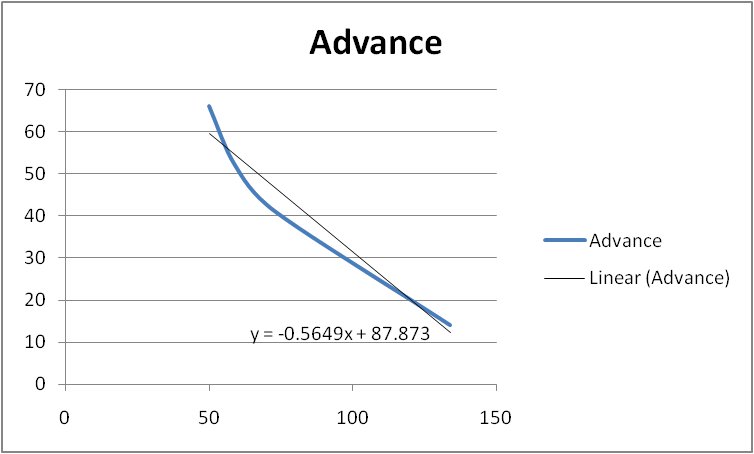
.  Are you looking for a plot of temperature vs voltage or temp vs voltage AND ECU output?
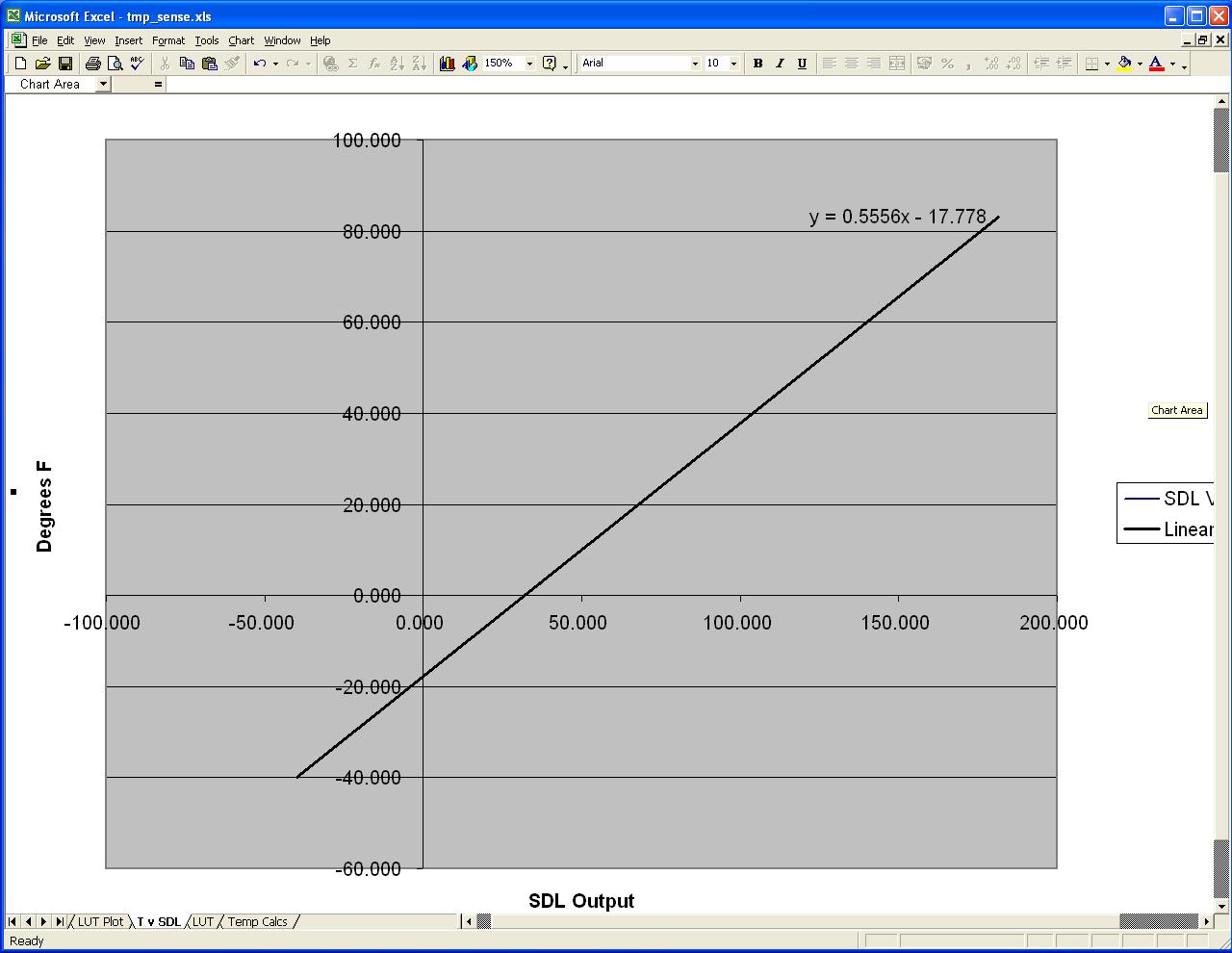
Regarding the O2 sensor and the calibration resistor - they appear to use different connections (I'm looking at the terminal callouts from the FSM) - there is one wire that uses same color code, but it connects on a different pin.

The way I understand it the output from the O2 sensor should show some variation whilst the output of the cal resistor would be a constant voltage, so connecting one in place of the other should (or would) probably throw a failed O2 sensor code.

-- Edited by fordem on Thursday 22nd of October 2009 02:36:27 PM

__________________


Guru

Status: Offline
Posts: 1351
Date:
Permalink  
 

I had yet another go at the temperature sensor problem, this time I plotted the diagnostic output against the sensor input in Fahrenheit - result!

WTS plot


The derived equation is:
             y = 0.5556x - 17.778

where x is the SDL output and y is the temperature in Fahrenheit. Allowing for tolerances in the A/D reference, sensor and input circuitry the equation is most likely to be 0.5x-18. So I'll put that into the code and that will be another job done.

__________________

1984 Suzuki SJ413K pick up, 1.6 16V Baleno engine
2000 Suzuki Vitara 1.6 8V, many mods
2004 Suzuki Ignis 1.5VVT 4Grip
2006 Suzuki Jimny 1.3VVT JLX+
and many more.

1 2  >  Last»  | Page of 2  sorted by
 
Quick Reply

Please log in to post quick replies.


Create your own FREE Forum
Report Abuse
Powered by ActiveBoard